Part of finding new applications for the Rift will come from a detailed understanding of how the whole system works. For many, it's enough to be told that it's done with lenses and software the corrects for the lens distortion.
A more detailed understanding can be useful though, especially when you're trying to make something render properly and having trouble with the distortion shader and it's settings.
Intent
The lenses on the Rift function by applying what's called a pincushion distorion to the view. This has the effect o making the display screen appear to occupy a wider field of your view. At the center of the lens, looking directly down at the screen there is no distorion. However, as the angle between the lens center and where the user is looking increases, the lens intercedes and reduces the actual angle to the panel. If you look 45° to the left, the lens is actually distorting the incoming light so that you might see light that is only 30° to the left from the LCD panel. These values are just demonstrative. If uncorrected this would mean that the further from the center of the image you looked, the more distorted it would be. |
| Pincusion distorion |
 |
| Barrel distortion |
Action
So how do you apply a barrel distortion to an image? Wikipedia has a paragraph or two on the topic, but it presents a more mathmatical approach to the topic and introduces more terms in the equation than are actually used in the shader. Stated simply
- Find the distance between the center of the distortion and the point you are rendering. We refer to this as r because it is the same as the radius of a cirle on which that point lies.
- Given an array of coefficients, multiply the radius raised to a certain power with each coefficient and sum the results of these multiplications. This gives us a value we will call the distortionScale.
- Multiply the original x and y values of the point you are rendering by the distortion scale. The new x and y values are the points in the original image which should be rendered at this point on the screen
That's it. Here is code that finds the distortion scale given a point relative to the center of the distortion:
uniform vec4 u_distortion;

float distortionScale(vec2 offset) {
    // Note that this performs piecewise multiplication,
    // NOT a dot or cross product
    vec2 offsetSquared = offset * offset;
    // Since the power to which we raise r when multiplying against each K is even
    // there's no need to find r, as opposed to r^2
    float radiusSquared = offsetSquared.x + offsetSquared.y;
    float distortionScale = //
            u_distortion[0] + //
            u_distortion[1] * radiusSquared + //
            u_distortion[2] * radiusSquared * radiusSquared + //
            u_distortion[3] * radiusSquared * radiusSquared * radiusSquared;
    return distortionScale;
}
It's similar to the HmdWarp() function in the SDK version of the shader, though it does no transofrmation of the input vector. Also, rather than returning another vector, it simply returns the scale itself.
So why people have issues with the shader? The reason is related to the extra transformation that's happening the SDK version of the code.
Coordinate Systems
Dealing with rendering inevitably means dealing with coordinate systems. Virtually all systems orient the X axis in the same direction, with values increasing as you move to the right. Most mathmatical systems also treat Y in a consistent fashion, with values as increasing as you move up.
Most low level computing APIs for dealing with images and rendering surfaces place the origin at the upper left of the image or surface, with Y values increasing as you move down. Fortunately, we don't typically need to worry about this. OpenGL takes care of any such transformation when writing to the graphics device, so for the most part we just need to make sure we flip image files vertically when we load them into OpenGL textures.
However, even within OpenGL there are multiple different coordinate systems, and the added issue of aspect ratios. Take a look at the Rift screen in terms of it's actual pixels, as your computer sees it.
In order to apply the shader, we want to render that offscreen buffer as a single texture taking up the entire screen while the shader is enabled. Doing this in modern OpenGL actually involves a significant amount of boilerplate code involving vertex buffers and vertex attribute pointers. For the purposes of illustration though we're going to use the old OpenGL 1.x API calls to do it.
glBegin(GL_QUADS);
glTexCoord2f( 0, 0); glVertex2f(-1, -1);
glTexCoord2f( 1, 0); glVertex2f( 1, -1);
glTexCoord2f( 1, 1); glVertex2f( 1,  1);
glTexCoord2f( 0, 1); glVertex2f(-1,  1);
glEnd();
This code doesn't inclued the binding of the texture, the setup of the shader, or the binding of the shader uniforms. It just lines up 4 texture coordinates with 4 vertex coordinates and tells OpenGL to draw a rectangle with that information.
It also illustrates the difference between texture coordinates and vertex coordinates.
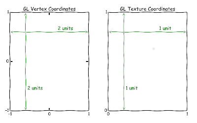 OpenGL vertex coordinates, by default go from -1 to 1. OpenGL texture coordinates go from 0 to 1, and when you're rendering a texture to the entire screen you get the above mismatch.
So why do we care about all this? Well, OpenGL fragment shaders have very limited amounts of information with which to render. When it comes time to render a single pixel three quarters of the way down the screen and three quarters to the right, we're fragment shader will be called and told to render the texture coordinate of (0.75, 0.25). From there we have to determine how to find the distorted coordinates to fetch from the texture. Passing what we have into our distortionScale() function above will not work. The coordinates we have do not represent an offset from the lens center, but rather from the lower left hand corner of the rendered surface. To get the value we need we have to do a bit of a waltz.
The first step is easy. We double the texture coordinate and then subtract 1 from both components. This moves us into the vertex coordinate space.
The length of the texture coordinate vector is now the distance from the center of the screen. However, that's not the offset we want. We need the offset from the point on the screen where the lens is located
 Se we subtract the lens center offset from our offset.
However, this still isn't sufficient to pass into our distortion scale function, because can't actually use our offset to calculate the radius. This is because our X and Y axes are not the same scale. Our X axis is actually 0.8 the size of the Y axis. So now we divide the Y component of our offset by the aspect ratio of 0.8.
Finally we have a vector we can pass into the distortionScale() function. Here is the transformation encapsulated as a function:
Once we've produced the distorted offset, we can't just plug it back into the texture. We have to walk back over the same steps we did to get here, in reverse order:
It also illustrates the difference between texture coordinates and vertex coordinates.

So why do we care about all this? Well, OpenGL fragment shaders have very limited amounts of information with which to render. When it comes time to render a single pixel three quarters of the way down the screen and three quarters to the right, we're fragment shader will be called and told to render the texture coordinate of (0.75, 0.25). From there we have to determine how to find the distorted coordinates to fetch from the texture. Passing what we have into our distortionScale() function above will not work. The coordinates we have do not represent an offset from the lens center, but rather from the lower left hand corner of the rendered surface. To get the value we need we have to do a bit of a waltz.
The first step is easy. We double the texture coordinate and then subtract 1 from both components. This moves us into the vertex coordinate space.
vec2 result = texCoord * 2.0 - 1.0;
The length of the texture coordinate vector is now the distance from the center of the screen. However, that's not the offset we want. We need the offset from the point on the screen where the lens is located

result -= u_lensCenterOffset;
However, this still isn't sufficient to pass into our distortion scale function, because can't actually use our offset to calculate the radius. This is because our X and Y axes are not the same scale. Our X axis is actually 0.8 the size of the Y axis. So now we divide the Y component of our offset by the aspect ratio of 0.8.
result.y /= u_aspect;
Finally we have a vector we can pass into the distortionScale() function. Here is the transformation encapsulated as a function:
vec2 textureCoordsToDistortionOffsetCoords(vec2 texCoord) {
    vec2 result = texCoord    // Convert the texture coordinates from "0 to 1" to "-1 to 1"
    result *= 2.0;    result -= 1.0;

    // Convert from using the center of the screen as the origin to
    // using the lens center as the origin
    result -= u_lensCenterOffset;

    // Correct for the aspect ratio
    result.y /= u_aspect;

    return result;
}
vec2 distortionOffsetCoordsToTextureCoords(vec2 offset) {
    vec2 result = offset;
    // Correct for the aspect ratio
    result.y *= u_aspect;

    // Convert from using the lens center as the origin to
    // using the screen center as the origin
    result += u_lensCenterOffset;

    // Convert the texture coordinates from "-1 to 1" to "0 to 1"
    result += 1.0;
    result /= 2.0;

    return result;
}
There are two more caveats to this. First is that this approach will shrink the rendered data, so that it no longer takes up the full screen, or even approaches the edges. In order to counteract this, a scaling factor is applied in the last function to the incoming offset. This scale is determined by finding the point on the screen you wish to reach, finding it's offset, finding the distortion value for that offset, and then finding the ratio of that distortion to the original distance. In practice, the offset ends up being the maximum X distance you want to render, so the offset will be one plus the lens offset distance. The SDK StereoConfig class has a GetDistortionScale() function that simply provides you the value, which gets used in the fragment shader method like this:
vec2 distortionOffsetCoordsToTextureCoords(vec2 offset) {
    vec2 result = offset / u_fillScale;

    // Correct for the aspect ratio
    result.y *= u_aspect;

    // Convert from using the lens center as the origin to
    // using the screen center as the origin
    result += u_lensCenterOffset;

    // Convert the texture coordinates from "-1 to 1" to "0 to 1"
    result += 1.0;
    result /= 2.0;

    return result;
}
The second caveat is that most rendering systems prefer texture sizes that are exact powers of 2 in both dimensions. If you create an offscreen buffer with dimensions like 640x800, most likely the underlying texture will be 1024x1024. This means a final scale factor must be applied to the texture coordinates so that the point into the sub-region of the texture memory that's actually populated.
The final version of the fragment shader can be here. It has a corresponding vertex shader here. The vertex shader is substantially less interesting, and it's sole purpose is to feed the texture shader while not doing any transformations of its own.
Bear in mind all of this code is intended to be illustrative, not performant or conforming to best practices for OpenGL.
Thanks for this comprehensive explanation!
ReplyDeleteGreat writeup. One nit-pick:
ReplyDelete"If you create an offscreen buffer with dimensions like 640x800, most likely the underlying texture will be 1024x1024. This means a final scale factor must be applied to the texture coordinates so that the point into the sub-region of the texture memory that's actually populated."
This isn't actually the case. It may store the texture at a larger resolution, but accessing pixels will still restrict the texture coordinates to the specified size:
https://www.opengl.org/wiki/NPOT_Texture
Good point. I'll try to update the post, and do a better job of hiding the fact that I haven't worked with OpenGL for about 10 years prior to getting my Rift
DeleteIf this is for a barrel distortion, why expose the radial distortion coefficients seperately, when wikipedia says it's a constant among all the coefficients? Is this a case of "good programming" by allowing the program to set those coeffients the same for barrel, and a geometric series for a moustache distortion? I really appreciate you writing this article, it's fantastic. Cheers.
ReplyDeleteIt's possible that mathematically speaking, it's not really a barrel distortion, but something more complex. The easiest way to test this would be to apply it to an image over a larger radius and see the behavior of the straight lines in the image. If that's the case then I suspect the use of the term 'barrel distortion' simply refers to the fact that within the constraints of the distortion as used by the Rift (r is never > 1.15) the overall effect is a barrel distortion.
DeleteHowever, I'm not really an expert in the area of optics or lenses. I'm mostly trying to make it easier for people to untangle the work required to distort from the work required to move the coordinate from one frame to another.